Using CAN database (CANdb or .dbc) files with OpenECU
Contents
-
Using CAN database (CANdb or .dbc) files with OpenECU
- Overview
- Unsupported features
-
Common questions and problems
- Another ECU on my network stopped transmitting a message. How do I deal with that?
- What happens if more than one message of the same ID are received in a single model iteration?
- Error messages are popping up, and I don't know what they mean.
-
My signal is not being received correctly in OpenECU, but the signal looks right in my CAN bus monitoring software
- The signal looks good on the CAN bus, but I'm seeing strange numbers when I view the variable in my calibration tool
- The signal looks good on the CAN bus, but OpenECU is always showing 0
- The signal looks good on the CAN bus, but it is clipped by OpenECU
- I recently changed the signal order (or added/removed signals) in my CANdb file, and now the signals are not being received/transmitted correctly
Overview
CAN database files provide a great way to organize and manage your CAN network. In general, OpenECU is compatible with CANdb files. However, there are a few restrictions as described below.
To use a CANdb file in your model, go to the Simulink library browser and select Pi OpenECU -> Communication Drivers -> CAN Drivers to get to the CAN block library. From there, you can drag and drop one of our CANdb blocks into your model.
Use pcx_CANdb_ReceiveMessage to receive a message using your CANdb file.
Use pcx_CANdb_TransmitMessage to transmit a message using your CANdb file.
See the CANdb demo for an example.
Unsupported features
OpenECU currently does not support the following features of CANdb files:
- Multiplexed messages
Anything in the Attributes part of the CANdb file. Some items in Attributes are described below along with how to work around this limitation.
GenSigStartValue to set initial value until first message is received.
OpenECU uses 0 as the initial value of each signal. Alternate behavior can be handled by your application software by using the rx_trig_flag output port of the pcx_CANdb_ReceiveMessage block to use a different initial value until the first message is received.
GenMsgCycleTime to set transmission rate.
See how do I set the transmission rate for CANdb messages? for further information.
Common questions and problems
We have gathered up a list of the most common support questions and problems and answered them below. We hope it helps.
Another ECU on my network stopped transmitting a message. How do I deal with that?
This is up to you to decide what is best for your application. You can implement a message time-out feature by using the rx_trig_flag output port.
rx_trig_flag will become 1 during the model iteration that a message was received.
rx_trig_flag will become 0 on the following iteration.
- All signal output ports will be held at the last-received value until a new message is received.
What happens if more than one message of the same ID are received in a single model iteration?
In this case, the following will occur:
- The output ports for each signal will contain the most recently received message.
- Signal data from earlier messages will be lost.
The overrun_flag output port will become 1 for one model iteration when this occurs.
Error messages are popping up, and I don't know what they mean.
This usually happens when OpenECU cannot find your CANdb file.
You CANdb file must be on your Matlab path.
- The easiest way to do this is to put your CANdb file in the same folder as your model.
- Alternatively, you can set you Matlab path to include the folder where your CANdb file is located.
My signal is not being received correctly in OpenECU, but the signal looks right in my CAN bus monitoring software
We normally see this question in the situations listed below.
The signal looks good on the CAN bus, but I'm seeing strange numbers when I view the variable in my calibration tool
I have a boolean variable, but my calibration tool is showing 65 for TRUE, but FALSE is correctly showing 0
I have an enumeration, and the calibration tool is showing completely different values than my defined enums
In this situation, the common culprit is a mismatch between the signal data type and the data type defined in the data dictionary.
- Note: Starting with OpenECU 2.4.0, a warning will be emitting during the build to alert you to the situation and the offending signals.
Here is how to solve the issue:
- Check your signal data type. The easiest way to turn on the Port Data Type display in your Simulink model, and either re-build the model or update the diagram (ctrl-D when your model is the active window).
- Next, check the signal data type against what is defined in the data dictionary.
- If the types do not match, change one or the other to match.
If the data dictionary is correct, you can insert a Data Type Conversion block (found in the Signal Attributes library) to convert the signal to the correct type.
- If the signal is the correct type, change the signal type in the data dictionary.
See help with data dictionaries for further information.
The signal looks good on the CAN bus, but OpenECU is always showing 0
or
The signal looks good on the CAN bus, but it is clipped by OpenECU
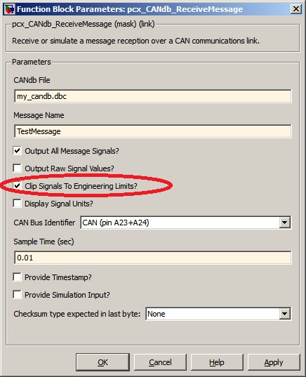
The usual cause for these two issues is due to the "Clip Signals To Engineering Limits" feature of the pcx_CANdb_ReceiveMessage block. To determine if this is an issue, do the following:
Double click the pcx_CANdb_ReceiveMessage block that is having the problem. That will open up the block dialog as shown below.

- Check if "Clip Signals To Engineering Limits?" is ticked (see red circle above). If so there are two options:
- Un-tick the "Clip Signals To Engineering Limits?" check box. OR
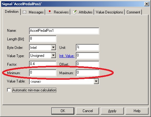
- Check the signal limits in the CANdb file (described below).
- Open your CANdb file in your CANdb editor.
- Find the problem signal and double-click it to open the signal editor. It should look like the following:

- Change the Minimum and Maximum values (circled in red above) to the correct values.
If you are still experiencing issues, double check your model for the following:
- The signals are all connected to the correct ports
- Be careful of crossing or overlapping signal lines
- Be sure the signal properties are set to "Exported Global" so the calibration tool can find the variable.
Be sure the signal is properly defined in the data dictionary.
- Be sure the name of the signal matches the name in the data dictionary.
- We recommend copy/paste instead of typing in both locations.
I recently changed the signal order (or added/removed signals) in my CANdb file, and now the signals are not being received/transmitted correctly
In this situation, the block works properly, but it may not work how you are used to Simulink working.
Behavior you are accustomed to
If you have a Subsystem block and you re-order the ports, Simulink automatically re-routes the wires outside of the Subsystem block to keep the port connections correct.
OpenECU block behavior
Simulink will not automatically re-route the wires to OpenECU blocks.
- This means that if you change the signal order in your CANdb file, you must manually re-route the signal wires going into the block.
Summary
If you ever add, remove, or re-order signals in a message, you must re-check the signal wiring into your block.
Copyright © 2022 OpenECU, All rights reserved