

OVERVIEW
Introducing M670
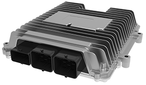
The M670 is a 154-pin high-feature Engine Control Module (ECM) designed to support Model Based Controls development for Gasoline PFI, Diesel Solenoid and alternative fuel applications up to 8 cylinders. The configurable M670 is perfectly suited for replacing an OEM ECM for engine development programs.
The Electronic Control Unit (ECU) integrates a broad range of Engine Control features such as dual ETC, quad V.V.T, VGT, dual Knock, UEGO, HEGO and more.
The M670 ECU can read a pulse-width based directional hall-effect crank sensor and providing a measurement of the current crank position even if the crank has stopped or moved backwards. This feature is useful for start-stop feature. With constant current drive feature the M670 can be used for Transmission Control Unit (TCU).
Dana’s systems, controls and software engineers are available to support application implementations from prototype to production.
OpenECU™ M670
Features
- Supports four-stroke and two-stroke
- 12V and 24V operation
- 8 boosted peak-and-hold injector outputs
- Build configurations for saturating or non-boosted injectors
- Programmable injector waveforms
- 8 smart spark coil outputs
- Two banks with independent high-side for overlapping injections
- Up to 12 injections per TDC
- Three H-bridge outputs
- Two generic high-side outputs
- Two wideband exhaust oxygen sensor interfaces
- Dual knock sensor interface
- Optional daughter board for circuit prototyping, cylinder pressure FPGA, etc.
- Protected against reverse supply and I/O short-circuits
- Supported platform software: OpenECU
Optional Control Software
- Torque-based engine control strategy
- Gasoline PFI, GDI, and diesel strategies
- Simulink-based control strategies
- Available black box or source code license
Injector Boost Supply
- Injector high-side control selectable battery or programmable 45V to 65V boost
- Boost supply total power output 120W
- Fully diagnosed and protected
Hardware Specifications
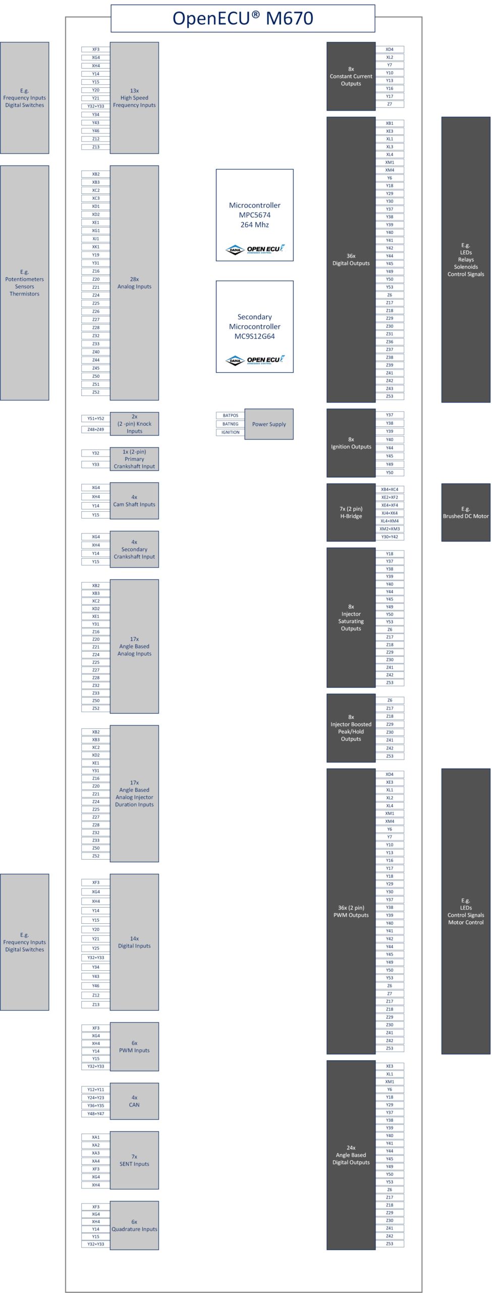
| Processor | MPC5674F |
| Clock Rate | 264MHz |
| Code Space | 3 MB |
| RAM Space | 128kB |
| Calibration Space | 128kB |
| Actuator Supplies | 2x 10A @ Vbatt |
| Sensor Supplies | 4x 250mA @ 5V |
| Input Pins | 54 |
| Output Pins | 49 |
| Communications | 4x CAN 2.0B |
| Single-ended analog input | 32 x 12-bit |
| RTD Sensor | 4 |
| Knock Sensor (differential) | 2 |
| Lambda Sensor (UEGO) | 2x |
| Lambda Sensor (HEGO) | 4x (only 2x available when using 2x UEGO) |
| Ignition Sense | 1 |
| Digital inputs (on/off general-purpose) | 5 |
| Digital, Frequency, PWM | 3 |
| Cam Shaft (VR/Hall single-ended) | 4x Hall only |
| Crank Shaft (VR/Hall differential) | 1x Hall (VR option) |
| H-Bridge or dual Half-Bridge | 1x 5A full-bridge & 2x 10A full-bridge or 4 x 10A half-bridge |
| Low-side GP, PWM (SM, VM, CTM) | 9x 0.2/0.5A lamp & relay, with monitoring of state, voltage, and fault status |
| Low-side GP, Spark (SM) | 8x (Smart Coil only) with monitoring of state; on-off mode for non-spark uses |
| Low-side GP, Injector (SM, VM, CM) | ·8x software-programmable waveform peak-and-hold: nominal 25A peak, 15A hold ·Co-processor current control with state, voltage, and current comparators |
| High-side Injector sources | 2x Injector High-Side outputs with programmable boost voltage phase, 25A peak |
| Low side GP (General Purpose) (VM, CTM) | 1x 8A, 2x 6A peak / 4A hold, with voltage and current-tripped monitoring |
| High-side GP (General Purpose) (CM) | 2x 8A up to 85°C, intended for source to low-side outputs, with current monitoring |
| Constant-Current (with inductive actuator) | 8x 2A |
| Internal Features | ·2 x 25A peak high side injector bank supply with boost. ·Daughter board slot |
| Optional Features | ·120W Injector boost power supply may be removed for lower cost ·FPGA duaghterboard for in-cylinder pressure measurement ·Customizable input bias configurations |
| Dimensions (mm) | 266 x 299 x 56.5mm |
| Material | Aluminum |
| Weight | 2.5kg |
| Connectors | Molex CMC 154-pin, 3-pocket |
| Vibration | ISO 16750-3 |
| Environmental Protection | IP69K |
| Location | Engine Compartment / Chassis |
| Supply Voltage (normal operation) | 12V or 24V |
APPLICATIONS
M670 Applications Include:
| Application | Description |
| Engine Control Module (ECM) | The M670 is suited for engine development, prototyping and production applications. Internal Combustion applications include:
|
| Replace OEM ECM | Engine development programs in certain scenarios require access to the ECM. The M670 is suited to replace OEM ECU providing complete development access to engine control design and development. |
| Transmission Control Unit | M670 is suited for transmission control of Dual-Clutch Manual (DCT), Auto Shifting Manual (ASM) and traditional automatic transmissions with two high current H-bridge drivers and up to 8 current controlled solenoid drivers. |
BLOCK DIAGRAM
CASE STUDIES
DOWNLOADS
- M670 Flyer
- M670 Technical Specification
- M670 Technical Specification Errata
- M670 Solid Model
- M670 Pigtail Harness
- M670 IO Schematics
- M670 Block Diagram
- M670 Assembly Drawing – PDF
- M670B Customer Pinout
To view the complete list of our product downloads, please click here.
MODULE COMPARISON
Compare ALL OpenECU Modules
| M110 | M130 | M211 | M220 | M6 Family | M670 | Actuation | M560 | M580 | |||||||||||
| Microprocessor | |||||||||||||||||||
| Primary Processor | SPC5534 | SPC5746B | MPC5534 | MPC5534 | MPC5534 | MPC5674F | MPC5746B | SPC5746 | SPC5746 | ||||||||||
| Primary Clock Rate | 80MHz | 80MHz | 80MHz | 80MHz | 80MHz | 264MHz | 160MHz | 160MHz | 160MHz | ||||||||||
| Primary Code Space | 512KB | 3MB | 768KB | 768KB | 512KB | 3MB | 2302KB | 3MB | 3MB | ||||||||||
| Primary RAM Space | 64KB | 256kB | 832KB | 832KB | 64KB | 128kB | 384KB | 256KB | 256KB | ||||||||||
| Primary Calibration Space | 256KB | 256kB | 236KB | 256KB | 256KB | 128kB | 128KB | 256KB | 256KB | ||||||||||
| Secondary Processor | SPC560P34 | SPC560P34 | SPC560P34 | ||||||||||||||||
| Secondary Clock Rate | 64MHz | 64MHz | 64MHz | ||||||||||||||||
| Secondary Flash Space | 192KB | 192KB | 192KB | ||||||||||||||||
| Secondary Calibration Space | 20KB | ||||||||||||||||||
| Secondary RAM Space | 12KB | 12KB | |||||||||||||||||
| M110 | M130 | M211 | M220 | M6 Family | M670 | Actuation | M560 | M580 | |||||||||||
| Power | |||||||||||||||||||
| Operating Voltage | 9V to 32V | 8V to 32V | 7V to 32 V | 7V to 32 V | 12V or 24V | 8V to 18V | 8V to 18V | 8V to 18V | |||||||||||
| Sensor Supply | 1x 5V @250mA | 1x | 1 x 5V / 250mA | 1 x 5V / 250mA | 2x 5V@250mA | 4x 250mA @ 5V | none | 2x 5V @200mA | 2x 5V @200mA | ||||||||||
| Standby Current | 0.25mA @12V | 0.25mA @ 12V | |||||||||||||||||
| Actuator Supplies | 1x 20A | 2x 10A @ Vbatt | |||||||||||||||||
| Output Protection | Short to Battery, Ground | ||||||||||||||||||
| Battery Input Protection | Overvoltage, Reverse Voltage | ||||||||||||||||||
| Survive Voltage | -28V to 36V | ||||||||||||||||||
| M110 | M130 | M211 | M220 | M6 Family | M670 | Actuation | M560 | M580 | |||||||||||
| Communication | |||||||||||||||||||
| High Speed CAN 2.0 | 2x | 4x | 2x | 2x | 2x | 4x | 1x | 4x | 4x | ||||||||||
| LIN (master)2 | 2x | ||||||||||||||||||
| M110 | M130 | M211 | M220 | M6 Family | M670 | Actuation | M560 | M580 | |||||||||||
| Inputs | |||||||||||||||||||
| Inputs (Analog or Digital) | 10x | 6x | 9x | 16x | 18x (Digital: 6x; Analog: 12x) | 40x (Digital: 5x switched, 3x Frequency, PWM; Analog: 32) | 4x | 40x (Digital: 9x switched, 3x PWM; Analog: 28) | 44x (Digital: 9x switched, 3x PWM; Analog: 32) | ||||||||||
| Reprogramming Enable (FEPS) | 1x @ -18V | 1x @ -18V | 1x @ -18V | 1x @ -18V | 1x @ -18V | 4x | |||||||||||||
| Differential VRS | 1x (2 pins) | ||||||||||||||||||
| Single Ended VRS | 2x | ||||||||||||||||||
| Frequency | 1x | ||||||||||||||||||
| Cam Shaft | 2x ±157V | 4x Hall only | |||||||||||||||||
| Crank Shaft | 1x ±157V | 1x Hall (VR option) | |||||||||||||||||
| RTD Sensor | 7x | 4x | |||||||||||||||||
| Knock Sensor | Knock Sensor | ||||||||||||||||||
| Lamda Sensor (UEGO) | 2x | ||||||||||||||||||
| Lamda Sensor (HEGO) | 4x (only 2x available when using 2x UEGO) | ||||||||||||||||||
| Ignition Sense | 1x | 1x | 1x | ||||||||||||||||
| M110 | M130 | M211 | M220 | M6 Family | M670 | Actuation | M560 | M580 | |||||||||||
| Outputs | |||||||||||||||||||
| Low Current Low Side Drives | Up to 1x 20mA & 2x 100mA & 6x 500mA | Up to 6x 500mA LSD | 12x 100mA, 3x 400mA, 14x 700mA, 2x 1A | 11x 100mA, 4x 400mA, 14x 700mA, 2x 1A | |||||||||||||||
| Medium Current Low Side Drives | Up to 4x 2A | Up to 4x 2A LSD | |||||||||||||||||
| High Current Low Side Drives | 4x 2.2A, 1x 3.2A | 4x 2.2A, 1x 3.2A | |||||||||||||||||
| 0-5 V Analog Output | Up to 2x 10mA | Up to 2x 10mA | |||||||||||||||||
| PWM Low Side | 2x 100mA | 2x 100mA, 2x 250mA & 6x 2A | |||||||||||||||||
| H-Bridge | 1x 5A | 2x 8A | 1x 5A full-bridge & 2x 10A full-bridge or 4x 10A half-bridge | 2x 50A peak or 10A | 1x 10A, 2x 5A, 1x 3.2A | 1x 10A, 2x 5A, 1x 3.2A | |||||||||||||
| High Side Switch | 1x 15A | 1x Hall (VR option) | |||||||||||||||||
| Low Side Injector | 1x 15A or 5A | 3x 5A peak/ 2A hold | 8x software-programmable waveform peak-and-hold: nominal 25A peak, 15A hold | ||||||||||||||||
| Current Monitors | 2x | ||||||||||||||||||
| Voltage Monitors | 2x | ||||||||||||||||||
| High Side Logic Outputs | 2x 1mA | 2x 1mA | |||||||||||||||||
| High Side Outputs | 4x 700mA | 4x 700mA | |||||||||||||||||
| Low Side General Purpose, PWM (SM, VM, CTM) | 1x 10A, 1x 2A, 1x 500mA | 9x 0.2/0.5A lamp & relay, with monitoring of state, voltage, and fault status | |||||||||||||||||
| Low-side General Purpose, Spark (SM) | 1x 8A | 8x (Smart Coil only) with monitoring of state; on-off mode for non-spark uses | |||||||||||||||||
| High-side Injector sources | 2x Injector High-Side outputs with programmable boost voltage phase, 25A peak | ||||||||||||||||||
| Low side GP (General Purpose) (VM, CTM) | 1x 8A, 2x 6A peak / 4A hold, with voltage and current-tripped monitoring | ||||||||||||||||||
| High-side GP (General Purpose) (CM) | 2x 8A up to 85°C, intended for source to low-side outputs, with current monitoring | ||||||||||||||||||
| Constant-Current (with inductive actuator) | 8x 2A | ||||||||||||||||||
| M110 | M130 | M211 | M220 | M6 Family | M670 | Actuation | M560 | M580 | |||||||||||
| Compatibility | |||||||||||||||||||
| Vibration | ISO 16750-3 | ISO 16750-3 | 6g random RMS | 6g random RMS | Ford IIIB - Severe | ISO 16750-3 | IEC 60068-2-64 | ISO 16750 chassis mount | ISO 16750 chassis mount | ||||||||||
| Environmental Protection | IP67 - Sealed | IP67 – sealed | IP67 | IP69K | IP67 Sealed/Gore vent | IP69K | IP69K & IPx8 Sealed/Gore vent | IP69K Sealed/Gore Vent | IP69K Sealed/Gore Vent | ||||||||||
| ESD | ±8kV - SAE J1113-13 | SAE J1113-13 | |||||||||||||||||
| Conducted and Radiated Emissions | CISPR25 Class 2 | CISPR25 Class 2 | |||||||||||||||||
| Conducted Transients | ISO 7637-2 | ISO 7637-2 | |||||||||||||||||
| Bulk Current Injection Immunity | ISO 11452-4 | ISO 11452-4 | |||||||||||||||||
| M110 | M130 | M211 | M220 | M6 Family | M670 | Actuation | M560 | M580 | |||||||||||
| Physical | |||||||||||||||||||
| Material | Plastic (PPA GF33) | PPA GF33 | Aluminum | Aluminum | Aluminum | Aluminum | Aluminum | Aluminum | Aluminum | ||||||||||
| Dimension in mm (W x H x D) | 138 x 130 x 42 | 138 x 130 x 42 mm (L x W x H) | 155 x 115 x 46 | 155 x 115 x 39 | 228 x 158 x 50 | 266 x 299 x 56.5 | 207 x 104 x 45 | 225 x 205 x 45 | 225 x 205 x 45 | ||||||||||
| Weight | 520g | 520g | 1.02 kg | 2.5 kg | 540g | 1.1 kg | 1.1 kg | ||||||||||||
| Connectors | 2 x 20 pin (Molex MX-150) | 2 x 20 pin (Molex MX-150) | 46 pin | 46 pin | 46 pin | Molex CMC 154-pin, 3-pocket | 1x 23 TE (AMSEAL) | Molex 112pin (1x 48, 2x 32) | Molex 112pin (1x 48, 2x 32) | ||||||||||
| Location | Chassis mount | Chassis mount | Chassis mount | Engine Compartment/ Chassis | Engine Compartment / Chassis | Passenger Compartment | Chassis/Passenger Compartment | Chassis/Passenger Compartment | |||||||||||
| Operating Temperature | ISO 16750-4 (-40°C to 85°C) | -40°C to 85°C | -40°C to 85°C | -40°C to 85°C | -40°C to 85°C | -40°C to 85°C | -40°C to 85°C | -40°C to 85°C | -40°C to 85°C | ||||||||||
| M110 | M130 | M211 | M220 | M6 Family | M670 | Actuation | M560 | M580 | |||||||||||
| Other | |||||||||||||||||||
| Program Status LED drive | 1x | ||||||||||||||||||
| Reprogramming Enable In | 1x @18V | ||||||||||||||||||
 Accessibility